Laying Tracks
There are more than one way to lay and attach the tracks on a model railroad. I will try to describe how I have constructed my N-scale railroad. I will mention as a general description that I use the principle of silent tracks and all tracks are Peco code 55. Minor differences can certainly occur depending on the track manufacturer and whether you use the set-tracks or not. But I will not take that into account, merely describe my own proceedings. Hopefully some of you will find this useful.
It is worth mentioning that I didn’t use the same approach on my old railroad. There I used Fleischmanns tracks and turnouts without any soundproofing material. When I ran trains with 6 or 7 wagons simultaneously (about 30 axles each) it was quite loud. It actually made so much noise that the rest of the family sighed with relief and made remarks about the nice and quiet, after running the trains for a long time and then stopped. It was for that very reason I chose to lay the tracks as silent as possible. And this is my way of doing it.
Silent tracks
Basically, I use Christer Engströms’s article from the book “Allt om Modelltåg 3” about silent tracks. For those of you who will start to lay silent tracks, I recommend you buy or borrow the book. I know it’s available at the central library in Stockholm. At least, that’s where I borrowed it the first time read the article.
I have the following layers on my silent track, from the bottom up.
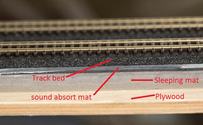
- 7 mm Plywood. I use this exclusively for all tracks. Further description of the tables that I use can be found on my building page for the railroad tables.
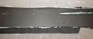
- Sleeping mat. I use the simplest possible, 8 mm thick. Acquired at the auto parts store (yes, I know!). This is glued to the plywood with standard wood glue. This is the only place that you may use the wooden glue! Above this layer, you cant use any hard materials as that will transfer the sound and the tracks wont be as silent as we wish
- Sound absorb mat. Also this from the auto parts store. This mat has a self-adhesive side. Pull off the protective film and attach it to the sleeping mat. Unfortunately attachment is not great, and in some cases it has been fully released. It seems that their quality is not the best. So do a simple check before you buy them.
- Woodland Scenics trackbed. On the track between the stations I use their standard trackbed, and inside the station areas or around major collections of turnouts I use one of their larger plates. However, it is crucial that these are not glued with white / wooden glue, but with a glue that becomes elastic. I make my own glue.
- Buy a tube of acrylic joint sealant.
- Take an empty ketchup bottle (or any other empty plastic bottle that you have).
- Press down the entire tube of acrylic joint sealant into the ketchup bottle + 1 dl of water.
- Shake until it’s all mixed
- Done!
- The base for the track is now finished. This leaves the course to secure the rail to the substrate. I use ordinary silicone. Press it and with a disposable plastic glove on your hand make a very thin layer. Attach the tracks and fix them in place with pins for bulletin boards
- Let is dry for a day or two.
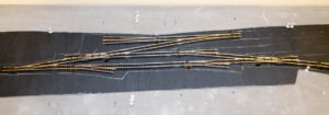
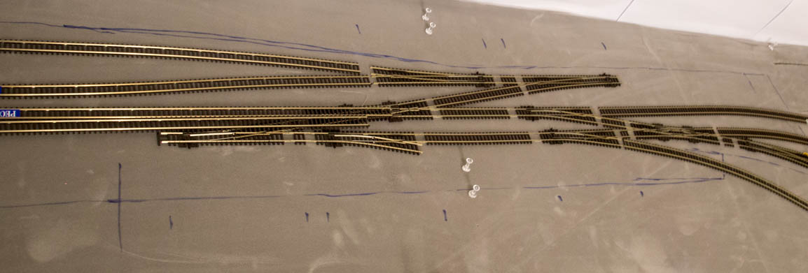
Track laying around turnouts
Laying track around turnouts is where the fun begins. As a lot of electrical connections is involved, and especially how to fix the turnout so the servo and servo holder works with it is a challenge. So I will not only describe how I fasten the turnout to the underlying materials, but also how to connect all the cables and mount the servo holders.
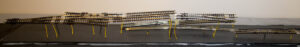
- The principle around turnouts is the same as for the normal tracks. So I will start from the point where the sleeping mat is in place. When it is, I lay out all the turnouts and all the tracks between them so I know what position they will be in. This is essential as it’s from this action that I will drill holes in the board for the servo piano wire.

- When all turnouts are in the right place, I mark where the piano wire will come and drill, and drills first through with a 1 mm drill and then from both sides with a 16 mm drill. Reason for drilling from both sides is to avoid splinters from the plywood under the sleeping mat. They are hard to remove without destroying the mat. You might think that 16 mm is a bit much, but this hole wont be seen after the woodland trackbed is in place, and it helps if the turnout isn’t in 100% correct position.
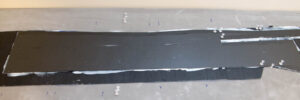
- When the holes in the sleeping mat is drilled, I put on the sound absorb mat and drill/cut out the same 16 mm hole in it.
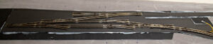
- Put back all the tracks and turnouts and verify that the 16 mm holes are centered under the turnout point. If it is, mark with a pen where the outer edges of the track will be. This is the mark I use to cut out the woodland track bed.

- Cut out the Woodland track bed so it matches the mark and fix it with the same elastic glue that I use for the normal track. You can find the recipe above under point 4.
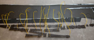
- Put all the tracks back, again… Mark where the exact position will be for all wires. Now this is where most mistakes are made. It’s so easy to forget a wire, and if you notice it to late, it might be a lot of extra work. So go over every single track, and verify that there will be power to them all. Keep in mind where the insulators are and don’t forget that if you use electrofrog turnouts, you also need power to the frog.
- Drill holes for all the wires, and cut with a small knife in the track bed above the 16 mm hole so the piano wire can go thru the track bed without interference. I use a 1.6 mm drill for the wires
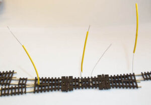
- Did you remember where all the wires should be? Not it’s the time to prove it. Remove all turnouts and tracks and solder all the wires. I use black from the common track and yellow for the side that is connected to the block detector. But I also use yellow for the frog connection. If I would redo all the wires to all the tracks, I would pick another color for the frog cables. But I wont change a standard that I use in the middle of everything. So I’m stuck with two yellow cables for two different function. Sucks, I know!

- We now need to verify that all pre-drilled holes for all the wires is in the right place. Put all the wires into the holes, and continue to put the all in so that the tracks are hovering above the track bed. This is one of those times when you usually comes up with new ways to combine curse words.
- Push all the tacks in and verify that they are in the correct position and that the small cut you made are directly under the point for the turnouts. If not, fix and adjust. This is the time when everything needs to be perfect.
- At this stage, I usually draw a line around all the turnouts to mark where I will put the silicon. I also mark where I should NOT put the silicone.

- Fasten the tracks and turnouts in the track bed. I use a ordinary silicone. Press it and with a disposable plastic glove on your hand make a very thin layer. Attach the tracks and turnouts and fix them in place with pins for bulletin boards.
- Let it try for a day or two.


Installing the servo holders
It’s not very hard to install the servo holder. You just need to be precise. 1 mm in the wrong direction can be what is required to go from success to failure. I have installed around 60 servo holders on my track so far, and this is the easiest way for me to do it.
- Put the piano wire on the servo holder through the 16 mm drilled hole, up through the track bed and into the little hole in the throw bar. It sounds easy, but this is actually the really hard part. From this point forward, it’s easy. I have two techniques to do this. One is just to look at the turnout and see when it’s through. If the turnout is close to the edge of track railroad table, it’s doable. But usually the turnout is in a bad position so your arms wont be long enough. In that case, I use a live video feed to my computer and just looks at the monitor. My Canon 6D camera handles that for me. But I’m sure a standard web camera with some decent resolution will do.
- When the piano wire is through the hole, you need to hold the servo holder in a position so that the point rails are right between the both rails. This is important, as this is the center position of the servo.

- Fasten the servo holder to the plywood board when the point rails are in the middle position. Just hold it steady and be careful.
- If you managed to fasten it correctly, you can now start to measure the end position of the servo. I use my servo tool for this. Once I have a description on it I will put it on some page here. What it does is let you control how many milliseconds the signal is. For those of you who don’t know how a servo works, the number of milliseconds can be translated to number of degrees the arms moves. Measure the both end positions, as you will need those in the servo decoder.
- Put the point rails back in the middle position and fasten the micro switches for feedback and polarization of the frog. As the pointrail is in the middle position, this is also the position when the micro switch should switch over. So just fasten them when they just switch over.


Whats left is to connect all the wires. Good luck on that! 🙂
I will create a page where I describe how I connect the power, and link it here once its completed.