If you are running a digital RR and wants to have some kind of controlled running with a help of a computer, you will need blocks. And you also need a way to detect if there is a train on that block. You need a block detector! This page describes the one I designed and is using all over my railroad.
A block detector is actually very simple. You measure if there is current going to the tracks. How you measure it is by feeding the power to the tracks thru two diods. Every diod will have a voltage of 0.7 volt over it, and two will give you 1.4 volt and that is enough to drive an optocoupler. So, train on the track, and the optocoupler is open, no train on the track, and the optocoupler is closed. Very easy! But an optocoupler as it self doesn’t help you very much. You need to connect that to a feedback modul that will send the change back to the computer and, in my case, TrainController.
One large and one small?
Well, yes. There are two versions. One with 16 inputs, and one with just two. But the number of inputs is not the major thing that is different with them. The one with only two inputs is designed to work after a reverse loop module. I put two input ports on this one, because I have more than once found me in a situation where I needed feedback on reverse loops for double tracks.
Compatible with two feedback modules
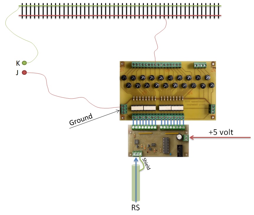
The block detector that you find on this page is compatible with two feedback modules. My own of course, but also the LDT RS-16-O feedback module. The LDT version requires that you also connect the ‘+’ cable on the side of the board, and feed the feedback module with the + connector in the middle. My own design doesn’t require that. You only have to connect J and – and skip the middle connector to the feedback module. I’m sure you can use other feedback modules as well, but I haven’t tried it out. Why not drop a comment with your experiences if you use these block detectors?!

No feedback connections
When using these block detectors, all tracks have a 1.4 lower voltage. That’s usually not really a problem. The problem comes if you feed turnouts and other parts of you railway where you don’t have feedback detectors and the 1.4 lower voltage that comes with it. The result would be that all the train accelerate over these tracks/turnouts. And that’s not really realistic if you ask me! So I have added diods that only feed the tracks with 1.4 lower voltage, but don’t have any feedback connections and no optocouplers.
Schematics

Component list
16-Inputs board
D1 to D20 – Diod bridge rectifier. One that can handle the current your trains use
R1 to R16 – 10 ohm
IC1 to IC4 – TLP620-4
2-Inputs board
D1, D2 – Diod bridge rectifier. One that can handle the current your trains use
R1, R2 – 10 ohm
IC1 – TLP620-2
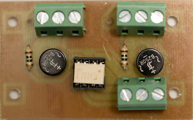
PCB design
As you can see, the finished circuit board does not look the same as the design picture. Thats because I redraw the circuit board and also uploaded the full Gerber files to make it simple to just order the PCB from an online creator. The ones in the pictures is the ones I’m running with and that I did myself back home. They have the same connections, just a different design.


Downloads
16-input block detector V1.1 Gerber
2-input block detector V1.1 Gerber