Using servos instead of normal turnout motor can be a challenge for the electronics. Comparing to the normal versions, these decoders cant not only enable/disable some of the outputs. They need to have the following features.
- Send a specific signal to every servo, so they are in the right position.
- Move slow, as you don’t want the servos speed, but instead something much slower
- Turn of power to the servos, if you turn of the power to the tracks.
- Turn on power to the servers, but not all at the same time. If you have 100 servo, you DON’T want them to get power at the same time. It will drain so much from your power source, so it will affect the voltage, and then the microprocessors restarts itself because of brown-out.
- Separate power connection to the servos. Not from the same source that gives power to the microprocessors.
- Memory to remember end-points. You don’t want the servo to move to much or to little
- Memory to remember last know position. No need to refresh/restart the entire railroad, and to move the arm to a start position every time you power on the servos
- A simple way to set end-points for the servos
This list is something that I have found out of experience. But now, all these features are included in my servo controller solution. So feel free to use it, and I hope you will get a good experience from using it.
I have created a very short movie that shows the movements of the servos and turnouts. I will give you an understanding about the operation on the track once they are installed.
Architecture
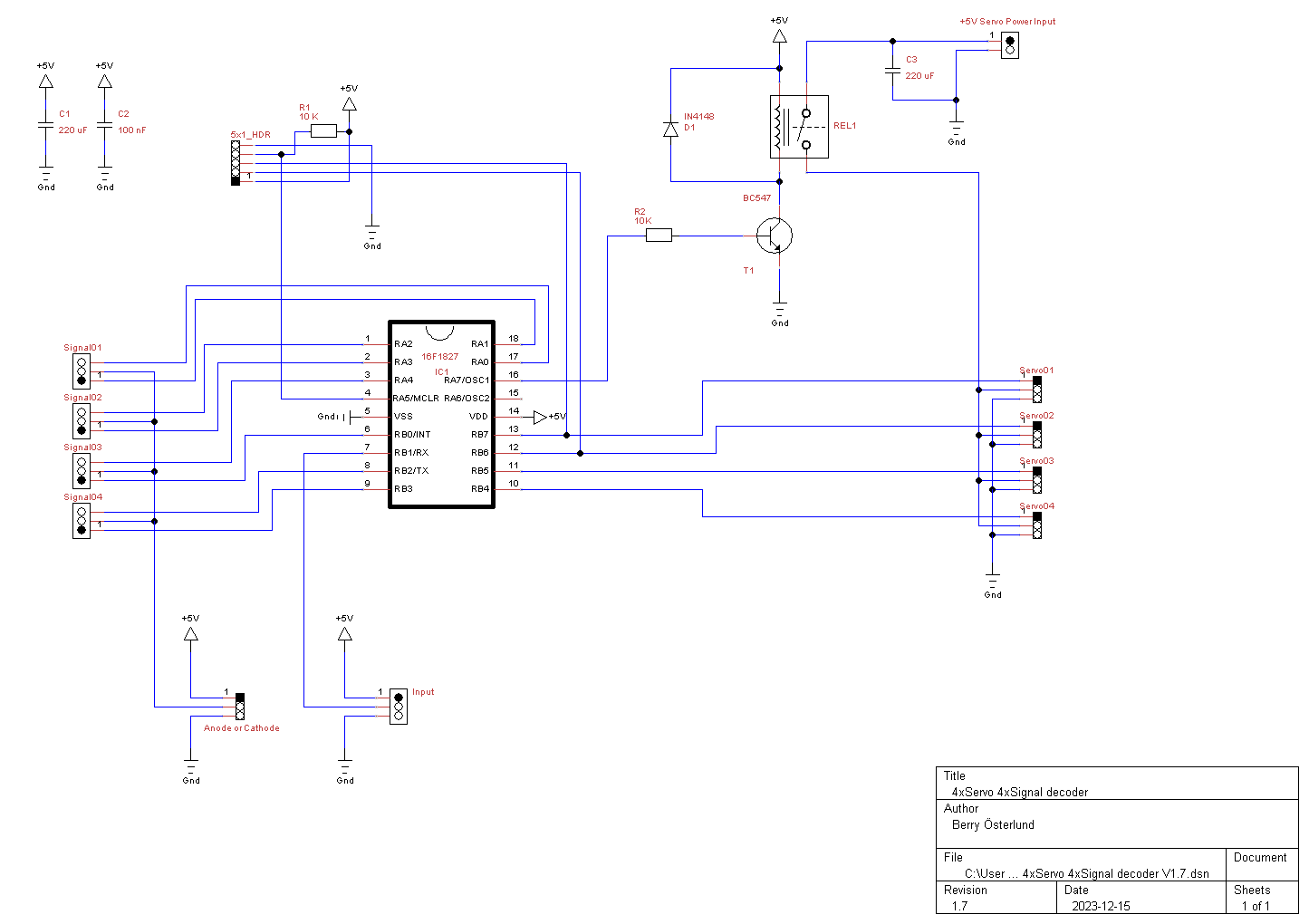
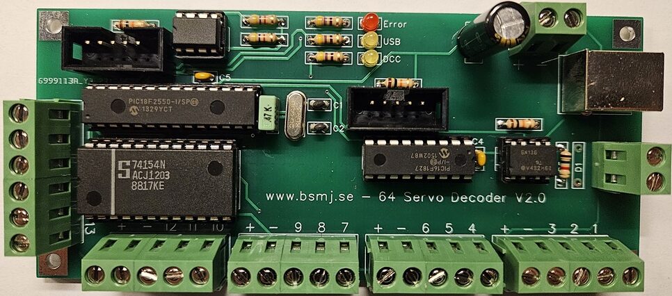
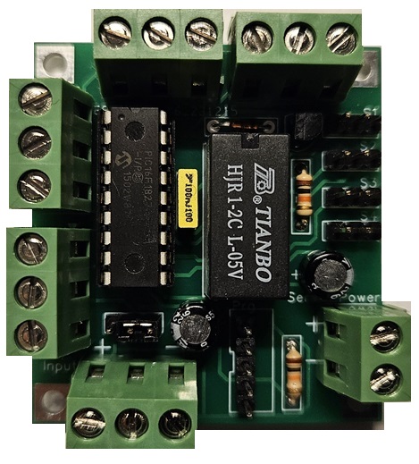
This servo decoder is built up from a central card and a number of smaller daughter cards. Every central card can handle 16 daughter cards, and every daughter card can handle four servos and four signals. Yes, you heard right. It can also handle signals. So a full blown out solution, you have a controller for 64 servos and 64 signals. On my railroad, I actually have three central cards, as they are under different tables. But not all cards are full on daughter cards. One of them have only four daughter cards.
USB and Raspberry Pi
All configuration changes regarding turnout addresses, servo speed, servo endpoint and so on is handled thru an USB interface, connected to a Raspberry Pi. I use the Raspberry Pi as that is a normal Linux computer, and it was already available on my railroad as I use it for my Lightning Solution. For those of you that don’t know what a Raspberry Pi is, it’s basically a very small computer. Roughly the size of a normal turnout decoder. I will, somewhere in the future add a full image to my Raspberry Pi to this page for downloads. Will make it much easier for new users to get started. Send me a comment to this post if your interested.
The micro controller and programming
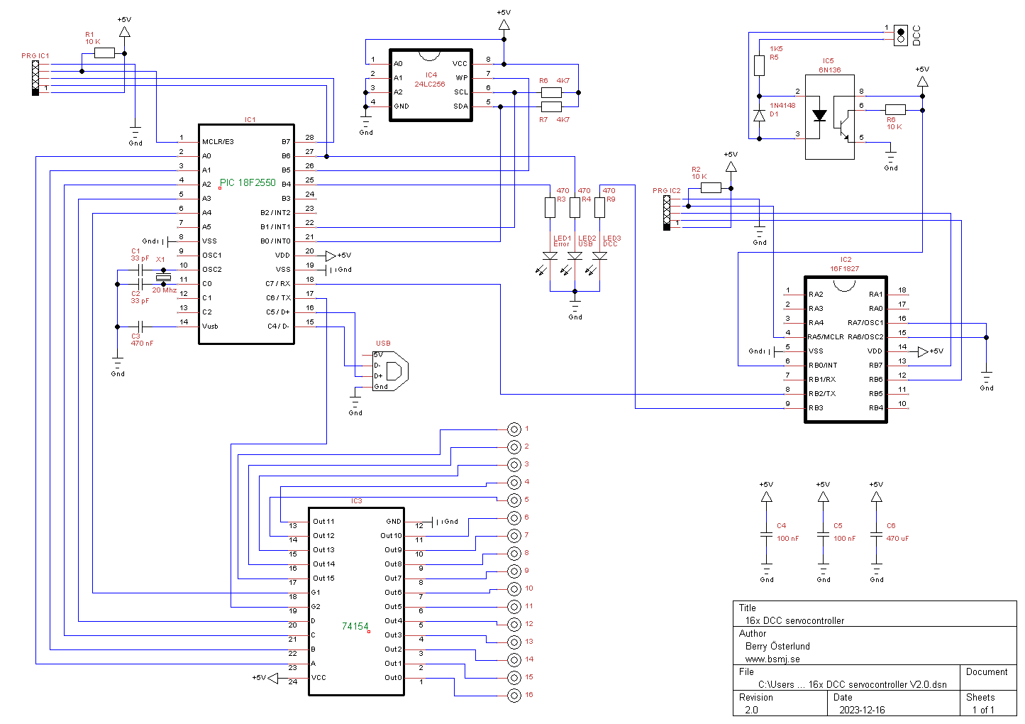
The central board is built around a PIC 18F2550. One of the features in this chip is the USB connection, and I use it for communicating to the Raspberry Pi for configuration changes. The program is written in MikroC from MikroElektronika. Now, one of the features is that the serialnumber for the USB device must be unique, and I set it the current timestamp at compile time. A very easy solution for me atleast, as the cards will have a unique serial number from that. For that reason, I have included 4 different HEX files in the download package. The olny difference between them is the USB serial number. If you connect to cards with the same serial number, linux will ID them as the same device and try to multipath them. Not so good. So just use different HEX files, and your safe. If you need more than four unique serial numbers, drop a comment and I can compile some more.
Connections and wiring
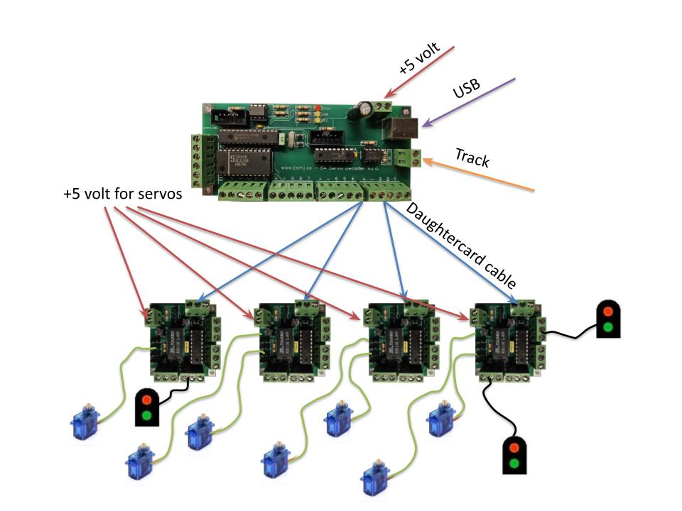
To proper wire the solution, this is what you have to do.
- Add +5V power to the Central card. Be aware of polarization, as there are no protection built in that will protect the micro controller if you do it wrong.
- Add +5V power to the daughter cards for the servos. The servo power and the +5V power to the central board have a common ground. So be aware of the polarization here as well. I recommend to use a separate power supply for the power to the servos. To avoid disturbance on the micro controller when turning on the servos
- Connect the daughter board to the central card. I use the kind of wire that usually is used to install larm systems at houses. A four wire cable, but I only use three of them
- Connect the servos to the daughter card. Ground (usually black on the servo cable) should be closest to the PCB edge, and the signal (yellow in my case) closest to the micro processor
- Connect the USB cable between the central card and the Raspberry Pi. I actually have a number of USB hubs located under all the tables that is connected to the Raspberry Pi. And this is something I can recommend anyway if you will build another one of my projects. I use the Raspberry Pi and/or USB a lot.
- Attach the Track cables.
Linux utility
The linux utility have a lot of functionality. You can do the following
- Set the name of the card
- Set speed of the servo
- Set min and max positions of the servo with hard values
- Use an interactive mode to set the min and max position of the servos
- Set the adress of the central card
- Show all settings, including addresses for every servo and signal
- List all connected cards
- Save and restore settings to/from a file
- Turn on the ident LED on the central card
For syntax and command help, run the following command
./servoSettings help
Schematic
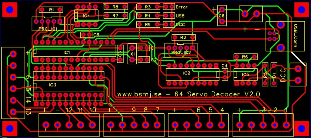
PCB design
CentralCard
Daughter card

Downloads
CentralCard V2.0 Gerber
DaughterCard V1.7 Gerber
4 x Servo DaughterCard HEX
16 x ServoCard Controller HEX
servoSettings.tar.gz