Using servos for turnouts is an electrical challenge. But’s also a challenge to get cheap, simple, good working holders for the servos. As I’m using the electrofrog turnouts from Peco with power to the frog, and together with position feedback on all turnouts I need to use two microswitches on all turnouts. This page contains the description on how I create the servo holders. So far, I’ve created around 60 of these holders, and they are all working fine for a very low price.
- Go to your local hardware store, and buy two wooden strips 15 x 27 mm, one aluminium profile, 90 degrees angled 12x12x1 mm and a board that you cut to 54 x 120 cm. I use 7 mm of plywood. This is the same plywood as I’m using in my railroad tables.
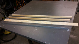
- Glu the wooden strips together with the plywood so the make a U, with an internal distance of 30 mm. That distance is based upon the servos I’m using. I was lucky and had two aluminum U-shaped stips, each with a width of 15 mm. Two besides each other and I hade the perfect setup to get an even 30 mm distance when I glued.
- Time for milling. Put in a pin-mill and remove 4 x 14 mm from both the strips on the inside. This is for the cable from the servo.
- Grind/saw so the end is completely perpendicular. I do this with my belt grinder. Fast and easy. If you don’t have a tool like that , it’s just a bit harder with the manual work. But it’s important that it’s perpendicular and even, as the aluminum part will be attached to the end.
- Take a measure from the end and mark two lines at 35 and 65 mm. The 65 mm line might be different, depending on what milling machine you are using. On my Bosch XXXX, with a 16 mm pin-mill, it’s 65 mm.
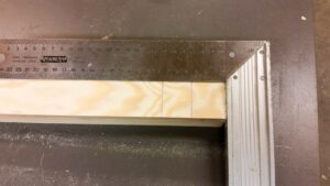
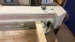
- Fasten a completely straight board / sheet / material at the 65 mm mark.
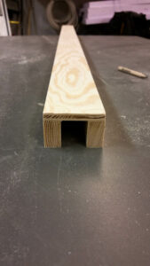
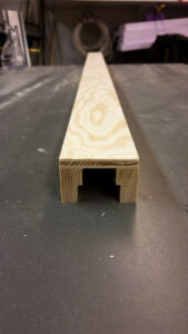
- Mill away 13 x11 mm by simply moving the cutter along the board that is attached a the 65 mm line. 13 mm from the edge and 11 mm deep.
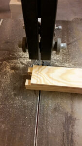
- Cut at the 35 mm line. The first servo holder is now sawn, milled and finished. Don’t forget to grind all the corners so you do not get splinters in your fingers.
- Repeat step 4 to 8 for the number of servo holder that you need.
- Saw aluminum strips so you get a number of small pieces 54 mm long. One for each servo holder.
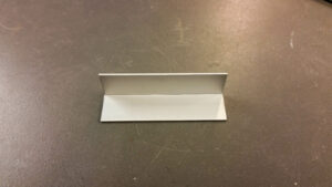
- Drill holes in the aluminum strip such that it comes in the middle of the wooden strips on the servo holder, as well as two holes in which the holder is fasted to the board underneath the turnout.

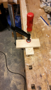
- Hold the servo in place and mark where the holes will be for the servo. You have to pre-drill those as there is so little material in which the servos are screwed. Without this, it cracks. Here I use the 0.8 mm drill and the supplied screws to the servo.
- Fasten the aluminum angle on the servo holder. Pre-drill these holes as well. I use 2.5 x 12mm screws for the aluminum strip, and pre-drill these holes with the same 0.8 mm drill.

- Drill the holes in the servo arms with a 1.3 mm drill in the third and sixth hole from the center.
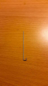
- Bend a 1.2 mm piano wire so you get the angle on the picture.
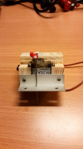
- Set the servo so that it is in the middle between the end positions, and so that the arm is perpendicular to the aluminum strip. Here, I use my servo tool and set it to 1500 us, and after that, I put on the servo arm so that it is perpendicular. You can do it manual as well. Just takes a bit longer and is not as precise. I will create a page for my servo tool in a couple of weeks.
- Put the piano wire in the innermost up drilled hole in the arm, and use the piano wire to mark where the hole in the aluminum strip will be. This hole is drilled with a 1.3 mm drill (0.1 mm wider than the piano wire. Very important).
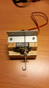
- Once the holes are drilled, I reinstall the aluminum strip to the servo holder. I then insert the piano wire so that it goes through both holes in the arm and attach it with cable ties so that it stays in place.
- The servo holder is now complete. Note that you should not put on microswitches at this stage. The servos must first be placed under the turnout, so you know how much the arm will move.


For a description on how to mount the servo holders onto the board under the turnouts, please check this page.