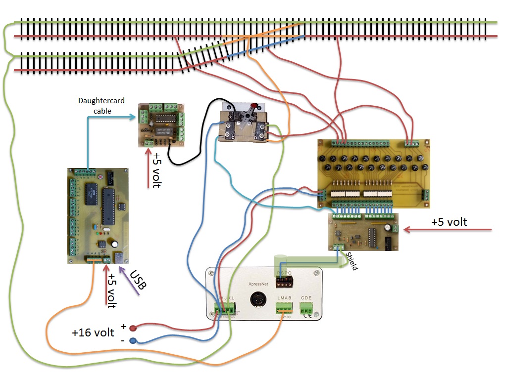
The entire layout is digital, with TrainController Gold in the middle. Central unit is a Lenz LV100 together with the USB/Net connection Lenz Li-USB-Ethernet to be able to connect TrainController with the railroad. All feddback modules, turnout decoders and signal decoders are designed and created by myself.
Feedback module
Decoder for 64 servos and 64 signals
Blockdetector
Powersupply

Every railroad needs a good powersupply. To use a small powersupply like the kind that goes together with a start-kit is out of the question when you have around 30 engines on the tracks at the same time, together with turnouts, lights, sound, computers and so on. So I decided to go with a larger powersupply that can deliver the power to the entire layout from one place. The one I have is exactly like the on on the picture, and according to specification, it should be able to deliver 15 Volts and 30 Ampere. But my readings give me 16 Volts. And that is just prefect for my N-Scale railroad.
But it’s not everything that requires 16 Volts. Almost all of the electronics I have designed myself requires 5 volts. In the begining, I put voltage regulators like the 7805 on all the boards. But to go from 16 to 5 volt generates a lot of heat and large heat sinks. So I decided to go with a smaller DC-DC converter that can give me 8 Ampere (peek 12 Ampere) and I’ve put that converter centrally, close to the LV100, PC-interface, Raspberry PI etc. The power is distributed to the entire layout in three cables, Ground, +5V and +16V.
Feedback connections
As the entire layout is controlled with the help of TrainController, it’s crucial that the block detectors is working flawless on all the tracks. I also have feedback connections on all turnouts, but I have chosen the easier solution here. I use only one feedback input port to detect the turnout position. So I cant detect if the turnout is “in-movement”. The other way to do it is to use separate input ports on the feedback module for the two different positions on a turnout. So if neater of them report true/on, the turnout is “in-movement” or have just failed. But that requires the double amounts of feedback modules and twice the cost.
The pros for using feedback connections on the turnouts is the ability to see if a turnout is not responding to the instruction or if it just failed for some reason. TrainController will detect this and select another route if possible, lock the exit from that block where the train comes from. This way, the we can hinder that a train goes into the wrong track with a collision as the result. Happened to me on my previous layout a couple of times.
Click for detailed information about my feedback module.
Turnouts
When I chose Peco as the brand for my tracks and turnouts, I tries Pecos turnout motors. But I didnt like them at all. The sound was like a pistol shot and the speed was so fast that you needed a high speed camera just to see it. I wanted a more natural and slow turnout change action.
So I decided to use servos to change my turnouts. I now have servos installed on all my turnouts and I’m very satisfied with the result. For more information together with a video showing the turnout action and the servo movement and all the schematics, PCB’s to create your own, please check my href=”https://www.bsmj.se/electronics/turnout-decoder-for-servos/”>dedicated page on the subject.
Signals
I dont have any signals jet, so there is not much to write about. But I know that I will be using Swedish signals and I also know that I have to create them myself. All the electronics to control the signals is already solved and is in place. The same decoder I use to control the servos can also handle the signals. The the circuit boards are already in place under the tracks and I only have to create the signals, mount them a connect the cables. More information will come once I start with the signals.
Schematics
To create a complete picture on how I connected the entire layout is not easy. There is a couple of 100 meters of cable under the layout so far, and I will be a very complex picture if I put everything in there. But I think an easier picture can be a good start on how I connected all the different components and there is additional information on my page for the turnout decoder and the feedback module together with the block detector.